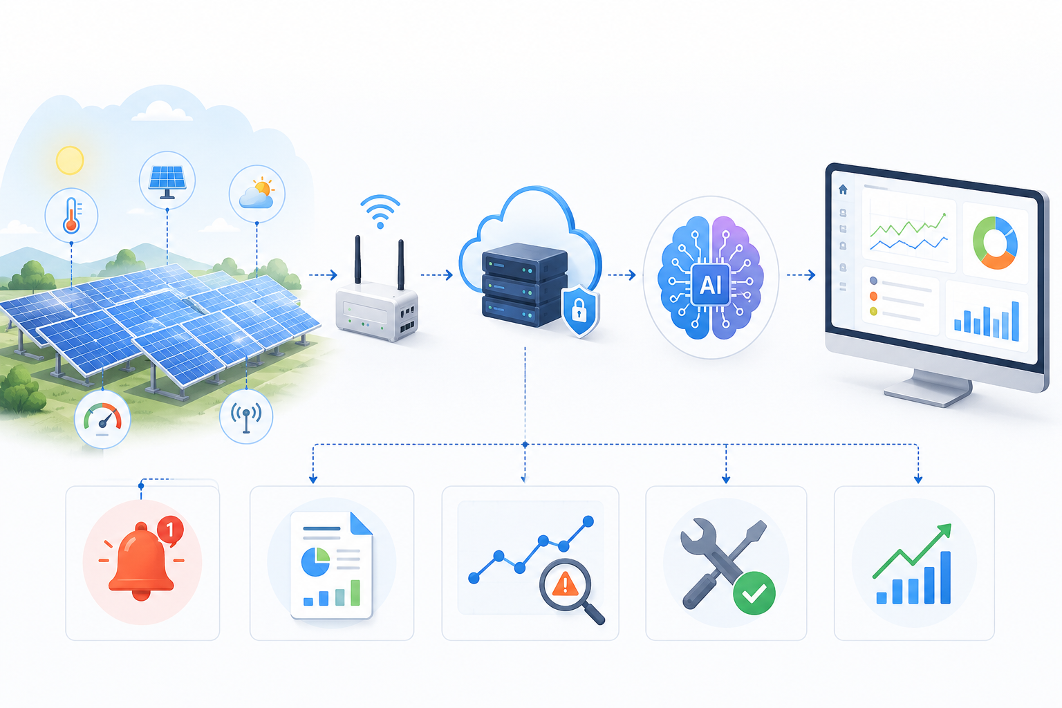


Weld inspection in metal fabrication has to deal with changing weld appearance, reflective surfaces, joint variation, and repeatable quality requirements. Computer vision for weld inspection can support this process by capturing weld images, analyzing visible characteristics, flagging suspicious areas, and creating a digital record for review. For Vancouver manufacturers exploring computer vision in metal fabrication, the strongest use case is not replacing every inspection method. It is adding a consistent visual inspection layer around clearly defined weld conditions. This article explains where that layer fits, its detection limits, and how to move from a controlled pilot to production use.
Where Computer Vision Supports Weld Inspection
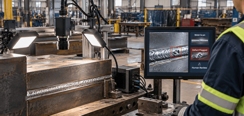
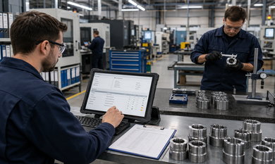
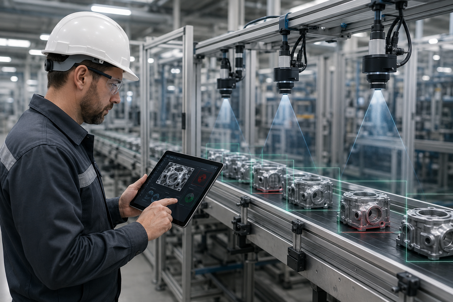
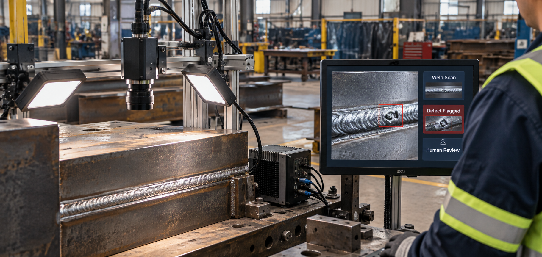
A machine vision weld inspection system sits at a defined point in fabrication. An industrial camera captures the weld under controlled lighting, the software identifies the weld region, analyzes relevant image features, and returns a result for the quality team.
The inspection point may sit on a manual workstation, semi-automated cell, or robotic line, depending on the production flow.
For fabricators already evaluating broader visual inspection, computer vision for quality control in Canadian manufacturing plants provides context on how cameras, image processing, dashboards, and production-system integration can work together.
Computer Vision Is an Inspection Layer, Not the Entire Quality Process
A camera and AI system should not be treated as the complete weld quality inspection process. Its role should be limited to what the system can observe and what the business has validated it to do. Qualified personnel, applicable procedures, and other inspection methods still remain part of the overall quality framework.
Which Weld Defects Computer Vision Can Actually Detect
The effectiveness of weld surface defect detection depends on whether the feature is visible in the captured image and whether the inspection setup shows it consistently. Depending on the application, cameras may help identify visible surface cracks, porosity indications, undercut, overlap, excessive spatter, bead irregularity, inconsistent profiles, or alignment problems.
Detection is never automatic in every condition. Surface finish, geometry, lighting, contamination, camera angle, and image quality all matter. A reliable AI-based weld defect detection workflow therefore starts with a narrow inspection target.
The same limitation applies to weld defect detection using computer vision. A standard visual camera analyzes information visible at the surface. It cannot see through a weld simply because AI is processing the image.
For internal discontinuities, ultrasonic testing, radiographic testing, or another suitable method may be required depending on the part, project specification, and governing requirements.
How a Computer Vision Weld Inspection Workflow Works
A useful automated weld inspection workflow can be organized around six practical steps.
- Capture the weld image. The camera records the weld from a repeatable position with lighting designed for the surface and geometry being inspected.
- Locate the inspection area. The software identifies the weld or predefined region of interest.
- Analyze visible characteristics. Image-processing and AI techniques examine features such as edges, texture, shape, bead profile, and surface patterns relevant to the task.
- Flag the result. The workflow may use states such as pass, suspected defect, or review required.
- Route uncertain cases to a person. A practical AI weld inspection process defines when an operator, welding inspector, or QA specialist reviews the image and findings.
- Record the outcome. The record can include the image, part or batch reference, weld location, timestamp, detected condition, and reviewer action.
The goal is to make the visual portion of inspection more repeatable, traceable, and easier to review.
Why Camera and Lighting Setup Matter as Much as AI
A computer vision system cannot analyze detail that is not captured clearly. In weld quality control automation, camera placement and lighting are therefore part of the inspection design.
Camera Position and Resolution
The camera needs a repeatable view of the weld area. Working distance, field of view, viewing angle, lens choice, and required detail should match the smallest visible feature being evaluated. Higher resolution alone will not fix poor focus or inconsistent positioning.
Controlled Lighting
Metal surfaces can create glare, shadows, and reflections, while fabrication environments add dust or residue. Controlled lighting reduces unnecessary variation so the system sees the weld more consistently.
2D and 3D Imaging
Conventional 2D imaging can work when the target is visible in texture or edge information. If the task depends more heavily on height, profile, or geometry, 3D vision or laser profiling may be more appropriate.
For projects that need a custom imaging and analysis pipeline, computer vision development services in Canada can support object detection, image segmentation, vision processing, and deployment around a defined manufacturing workflow.
Where AI Ends and Human Review Begins
Computer vision can classify, measure, or flag what it has been designed and validated to inspect. That is different from saying an AI result is automatically the final acceptance decision for a welded component.
A safer workflow uses vision software to identify suspicious regions, preserve inspection images, and prioritize cases that need attention. Qualified personnel can then review exceptions and apply relevant procedures or acceptance criteria.
Build Review Rules Before Deployment
Teams should decide what happens when image quality is poor, confidence is low, weld geometry falls outside known conditions, the system detects an unfamiliar pattern, or a suspected defect is found.
Canadian fabricators also need to keep applicable welding and inspection requirements in view. The CWB Group's CSA W59:2024 update notes that the 2024 edition of CSA W59 was published in March 2024 and includes updated welding and inspection requirements, including requirements for encoded phased-array inspection. CSA W59 is not a computer vision standard. The broader point is that automated visual inspection must sit inside the quality and inspection requirements that apply to the job.
How Vancouver Fabricators Can Start with a Computer Vision Pilot
Start with one repeatable inspection problem rather than a plant-wide deployment.
Start With One Repeatable Weld
Choose one part family, weld type, inspection station, or recurring visible condition. A narrow pilot makes it easier to control imaging and compare results with the current inspection process.
Define What the System Needs to Detect
Document the visible conditions that matter and what should trigger a review. This prevents the project from drifting into vague goals such as detecting every bad weld.
Collect Real Production Images
Training and validation data should reflect normal variation, including acceptable welds, realistic surface conditions, different production runs, and known defect examples where available.
Validate Against the Existing Process
Compare the system's findings with the current inspection method. Pay attention to false alarms and missed defects. If performance changes with a particular joint, material, angle, or surface condition, treat that as a deployment constraint to address.
Add Human Review Before Scaling
Define who reviews flagged cases, what information they receive, and how the final result is recorded. Expand only after the workflow performs acceptably for the intended task.
Connecting Weld Inspection Results with Production Systems
A defect alert becomes more useful when it can be traced to the part and production context that produced it. Inspection records can include the captured image, part or batch reference, weld location, detected condition, inspection status, timestamp, and human review outcome.
Depending on the plant architecture, those records may connect with a PLC-controlled workflow, manufacturing execution system, quality-management system, or production dashboard. Not every fabrication shop needs an MES. The integration should match the systems already used to manage production and quality.
Traceability can help teams investigate recurring patterns by part family, station, weld type, shift, or production period, but patterns alone do not prove root cause.
Moving From a Pilot to Production Use
A pilot that works under controlled conditions still needs production validation. Before expanding to more welds or stations, teams should review lighting changes, camera contamination, edge cases, new materials, different joint geometries, processing time, network reliability, and inspector feedback.
For companies that need a custom deployment around existing equipment and software, an AI development company in Vancouver can help connect the vision pipeline, review interface, data storage, and manufacturing integrations without forcing every plant into the same architecture.
Frequently Asked Questions
Can computer vision detect weld defects?
Yes. Computer vision can identify visible weld characteristics and flag suspected surface defects when the imaging setup and inspection logic have been designed for that weld and production environment.
What types of weld defects can machine vision identify?
Depending on image quality and geometry, machine vision may help identify visible surface cracks, undercut, porosity indications, spatter, overlap, bead irregularity, and alignment issues.
Can computer vision detect internal weld defects?
Standard visual computer vision is mainly suited to surface-visible information. Internal discontinuities may require ultrasonic testing, radiographic testing, or another suitable inspection method.
Can AI replace a human weld inspector?
AI can automate defined visual checks and prioritize review, but qualified people may still be needed for exceptions, interpretation, acceptance decisions, and inspection tasks outside the validated vision workflow.
Conclusion
Computer vision can make weld inspection more consistent when the project starts with a clearly defined visual task, controlled image capture, realistic validation, human review, and integration with the existing quality process. Theta Technolabs' published computer vision stack includes OpenCV, YOLO, and PyTorch, which can support custom inspection and image-analysis workflows when they fit the use case. For questions about implementing computer vision for weld inspection in your fabrication workflow, contact us at sales@thetatechnolabs.com.